Raspberry Pi Pico W CWWW Controller - Part 1
Background and Motivation
In early 2023, I started getting more interested in home automation, with one of my first major projects involving using Home Assistant’s built-in Flux integration to control the color temperature of my new smart bulbs throughout the day, as well as automatically turning on the bedroom lights in the morning to help encourage me to get out of bed, and turning the lights off when I leave home.
While I have not yet swapped out all my traditional lights for smart bulbs with tunable color temperature, I have a set of over-desk lamps that I would like to have automatically change throughout the day. The design is pretty common on Amazon; it has two arms, a 12V power supply, and a hard-wired controller that lets one adjust the brightness in a fixed number of steps or cycle the color temperature between three different presets.
While the lamps work fine, they have some drawbacks that have become more annoying as I adopt more smarthome features. The biggest issue is that I often find myself fishing for the cord to either adjust the color temperature, or to turn it on and off. Given that I already have both my smartphone and physical switches that can control my other smart lights, I would like the ability to control these lights from Home Assistant, which would let me automate the color temperature and let me toggle the lights from other switches and remotes, or from my phone.
Lamp Operation
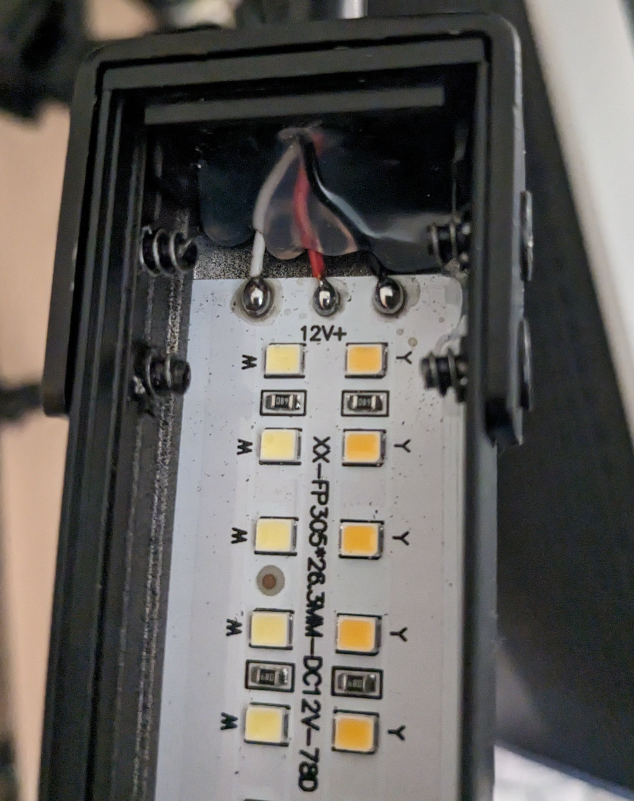
Before selecting parts, I first quickly disassembled (as best I could) the desk lamps, in the hopes that I could reuse the existing controller. Unfortunately, the plastic casing of the controller was extremely stubborn and refused to be pried open. I let the controller aspect go and instead focused on the actual lights themselves. After opening the lamp by removing the ends and sliding back the diffuser (Which was remarkably easier than the controller attempt), I found that each side of the lamp contained a prefabricated module containing two rows of 12V LEDs, one warm, one cool, sharing a common positive anode. This means that to control the brightness, the cathode end is where we need to modulate the LED state to adjust brightness and temperature.
Using the Pi Pico W with ESPHome
Having previously used a Raspberry Pi Pico W for another project, I felt confident that it would work well for this project. Granted, it’s not the lowest-power IoT board out there, but it’s easy to obtain, has decent documentation, and has fairly good ESPHome support available. This means we can leverage existing ESPHome primitives for many aspects of this project. Of note, we can use the CWWW Component to handle most of the heavy lifting, with the rp2040_pwm handling the actual PWM using the Pico’s built-in hardware PWM.
While we can control the lamp remotely with this configuration, I also wanted to maintain the existing button-based functionality for turning the lamp on and off, increasing or decreasing brightness, and cycling through color temperatures. Configuring extra buttons in ESPHome is fairly straightforward, but requires some additional considerations when designing the hardware. Altogether, this is what the ESPHome .yaml configuration looks like:
esphome:
  name: desk-lamp-1
  comment: "Desk Lamp"

logger:
  level: DEBUG
  baud_rate: 115200

rp2040:
  board: rpipicow
  framework:
    platform_version: https://github.com/maxgerhardt/platform-raspberrypi.git

wifi:
  networks:
    - ssid: !secret ${wifi_ssid}
      password: !secret ${wifi_password}

api:
  password: !secret ${ha_api_password}

light:
  - platform: cwww
    name: 'Lamp'
    id: lamp
    cold_white: cool_pin
    warm_white: warm_pin
    cold_white_color_temperature: 6000 K
    warm_white_color_temperature: 3000 K
    constant_brightness: true

output:
  - platform: rp2040_pwm
    pin: 16
    id: warm_pin
    frequency: 1000Hz

  - platform: rp2040_pwm
    pin: 18
    id: cool_pin
    frequency: 1000Hz

  - platform: gpio
    id: board_led
    pin:
      number: 32
      mode: output
Circuit and PCB Design
Even with good software support, the Pico cannot drive the lamp directly with its 3.3v output. Furthermore, the 12V power supply is not compatible with the Pico’s 3.3-5V accepted input voltage. In order to control this lamp, additional hardware is required to control the 12V power lines to the cool and white LED strips separately using the 3.3v output of the Pico’s GPIO.
When designing the custom hardware, I had several requirements that influenced the design:
- Capable of handling 2A of current through the board and into the lamps without overheating,
- Efficiently convert 12v to 3.3v for powering the Pico,
- Accept four button inputs for on-device user control
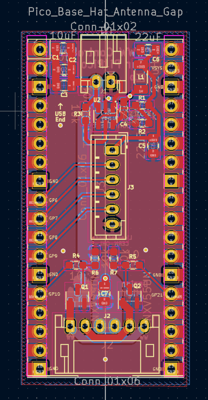
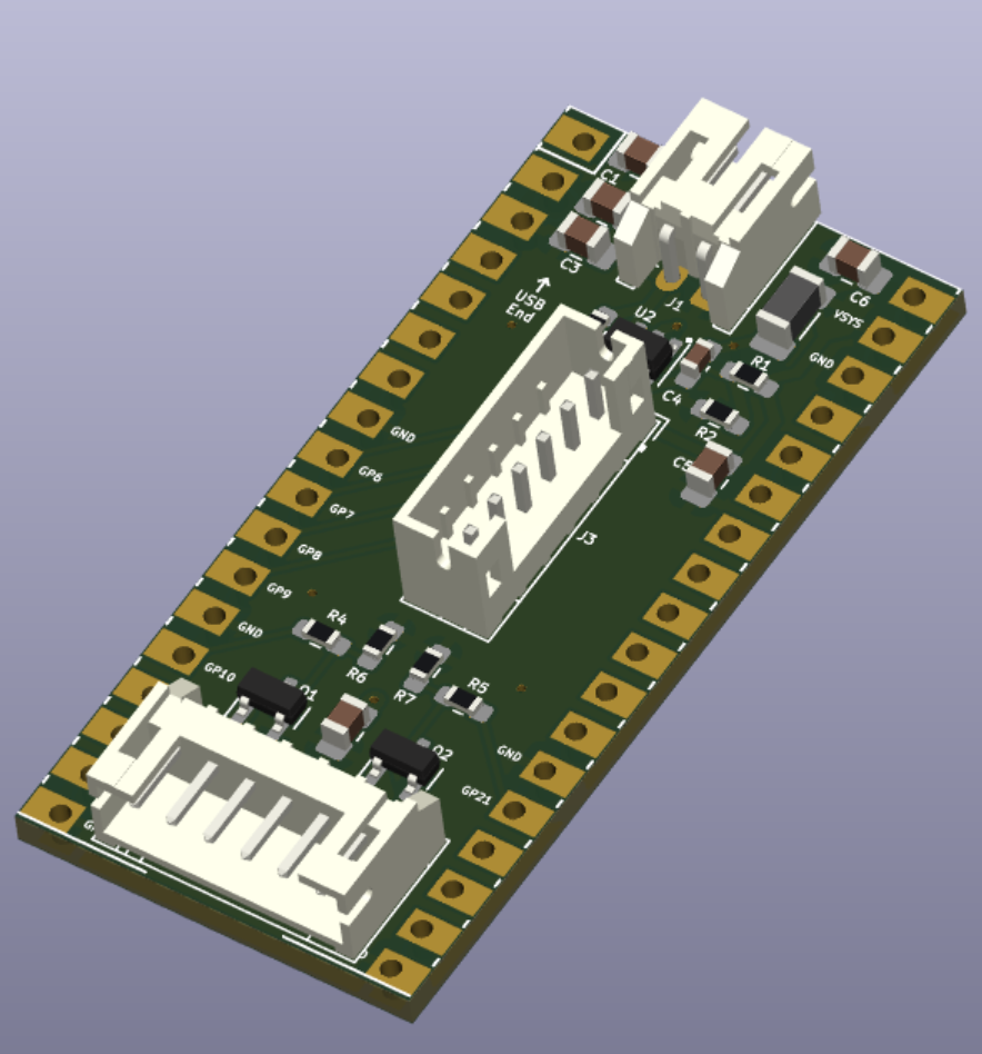
I opted to attempt to create a “hat” form factor for this board; this would maintain relative compactness, and be easy for others to use if I were to produce more copies of this board in the future. Also, it would allow packaging the components in a form factor not too much larger than the existing in-wire controller. I ended up modifying Nicolò Carandini’s KiCad Pico W footprint for this project, mainly to provide an airgap for the Pico W’s PCB antenna.
Starting with the power supply, I first found a reference design for the TI TPS565208 buck-boost power regulator, which I adapted for the top of the board using appropriately-sized components. Then, it was just a matter of finding the right MOSFETs for controlling the connection on the cathode end of the LED strips, and adding some buttons for control.
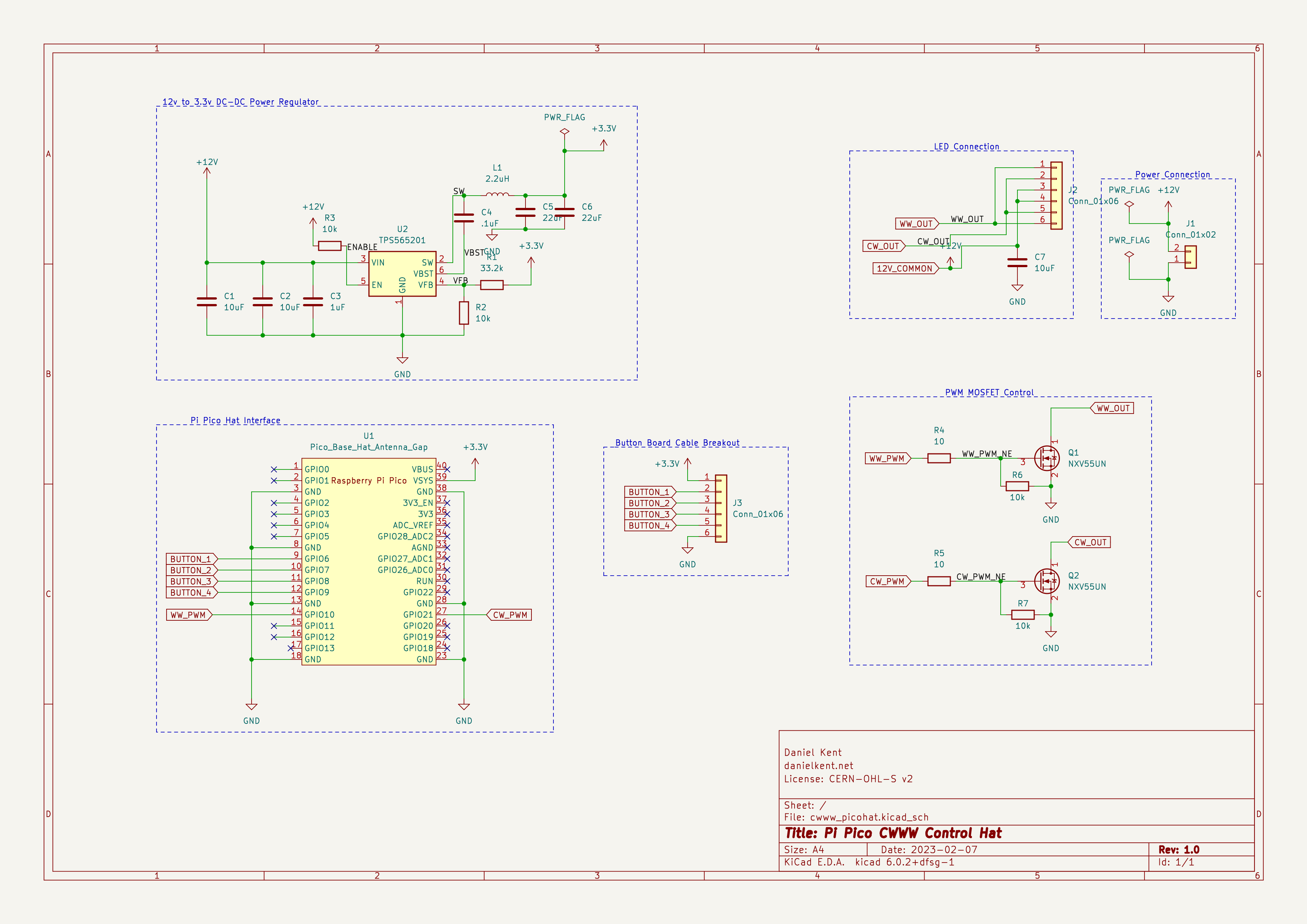
When laying out the PCB, I quickly discovered that fitting all of the components including the buttons was not feasible. I opted to create a second breakout board that would house the buttons. I replaced the buttons in the schematic with a 2.0mm pitch JST connector (specifically the vertical B6B-PH-K-S variant). I used similar connectors for the power input and lamp output pins. The JST PH pins are rated for 2 amps each in their specifications, which is also the maximum current for the power supply.
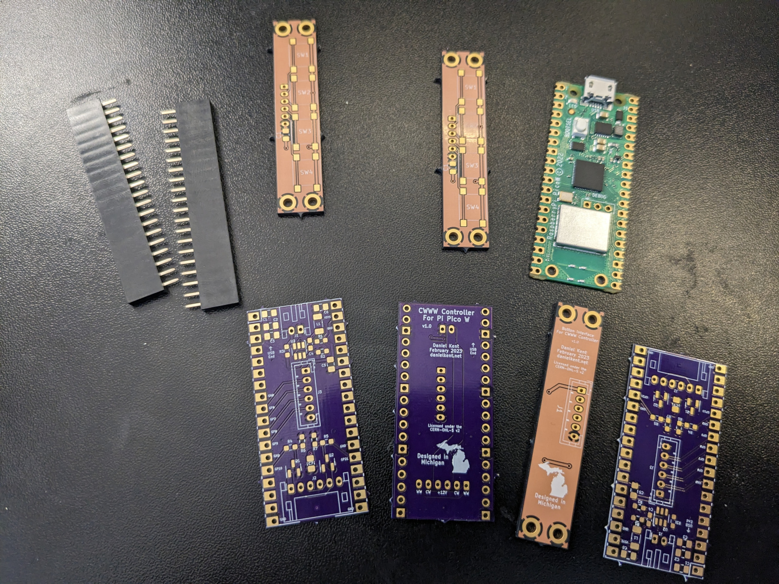
I ordered the boards from OSH Park, with the main board manufactured with their 2 Oz copper process to increase the current capacity, which hopefully wwould reduce or eliminate any heat issues from current flow. I tried out the After Dark process for the button boards since I was already going to be waiting extra time for the 2 Oz process on the other boards; while they do look unique, I think I would use the standard process in the future.
After some mishaps and a lost package, I finally received the PCBs, ready to populate!
Next Steps
Now that I have the parts and the PCBs, I am ready to assemble the boards. Once the PCBs and ESPHome configuration has been thoroughly vetted, all that remains is to design a case for the controller boards, then release the project to the public. I plan to release the board design under the strongly-reciprocal CERN OHL v2.0 license, mainly to prevent others from taking my design and reproducing it without attribution.
Stay tuned for Part 2, where I’ll show the process of assembling and testing the first prototypes.