Raspberry Pi Pico W CWWW Controller - Part 2
Assembly
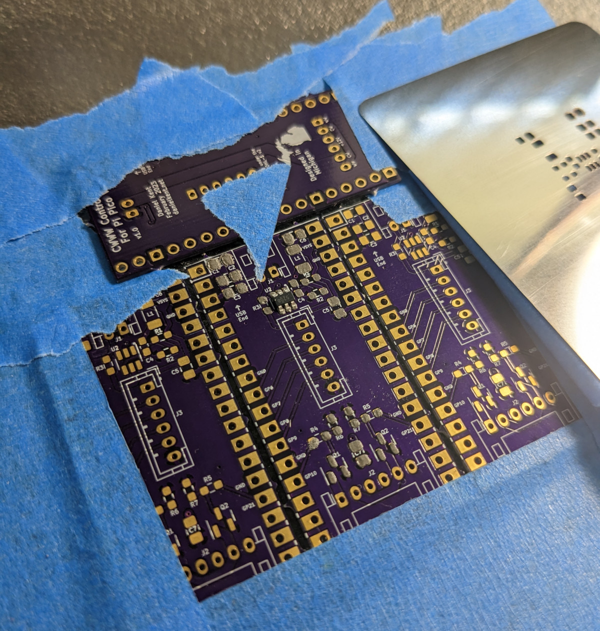
Finally, assembly and testing day was here! Using a friend’s borrowed solder reflow oven, I carefully applied solder paste, placed all the parts for one CWWW hat and one button interface, popped them in the oven, and waited.
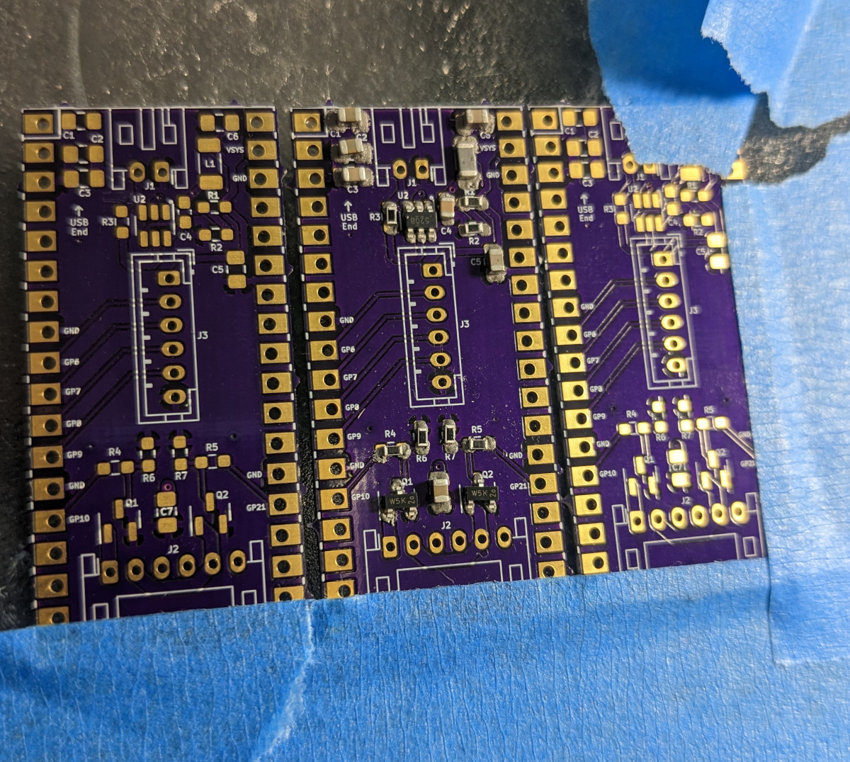
The reflow went pretty well, though the 0.1uF capacitor did adhere to the wrong pad since I chose to use hand solder pads. A quick rework with hot air got the capacitor back in the right place.
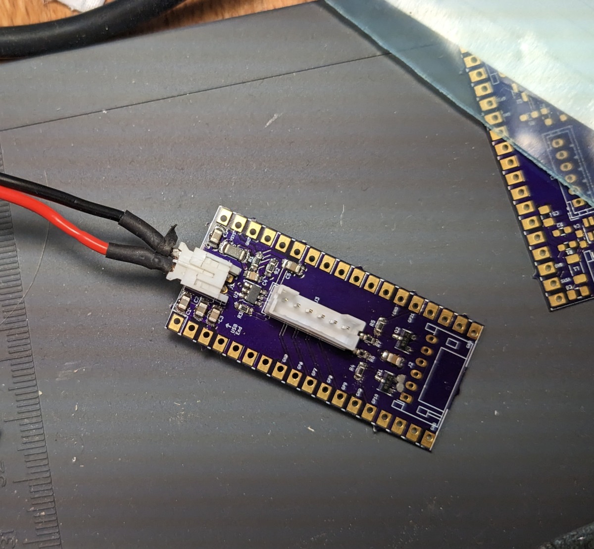
Before I added the rest of the connectors, I decided to test the output voltage of the board before connecting it to the Pi Pico W. After all, I didn’t want to fry any more components than I had to if I somehow got the circuit wrong! I did solder on the two pin input JST power connector to make it easier to plug and unplug the leads coming from the power supply. After fabricating a test lead, it was time to test!
Initial Testing and Troubleshooting
I set the power supply to 12 volts, limited the current, plugged the test leads into the board, then enabled power. Nothing spectacular happened, which was a promising start. For my next test, I checked the voltage across VSYS and ground. However, I found the voltage was hovering around 0.9 volts, far lower than the 3.3 volts I was expecting. Not good.
I quickly turned off power and inspected the board. Everything appeared to be soldered in place, though there were some tiny solder beads around some of the pads, likely a result of choosing hand solder footprints. I checked for connectivity and shorts, and found nothing obvious.
At this point, I wondered if I had designed the circuit wrong. I pulled up the reference circuit, and found that I had followed every single design criteria. It was only when I pulled up the PCB schematic in KiCAD that I found what was wrong: a missing ground connection in one of the feedback resistors. That would do it!
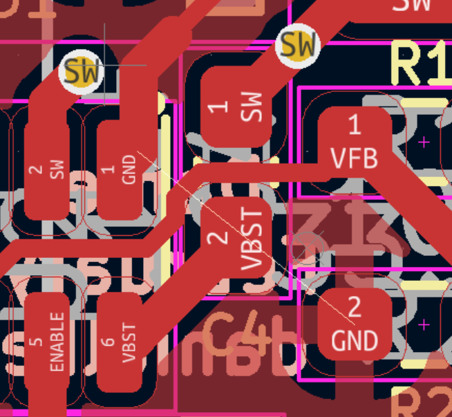
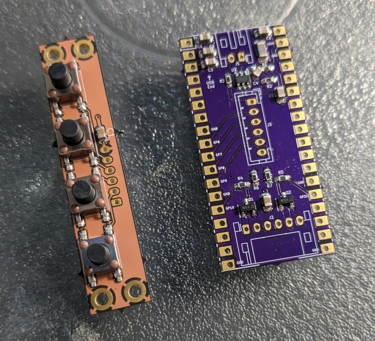
I quickly bodged a connection between the ground pins of R2 and C5, then tried turning the board on again. Without a load, I was now getting 3.8 volts! I assumed that the higher than expected voltage was a result of having no load, and regardless was well within the 1.8-5.5 input voltage tolerance of the Pico W. At this point, I went ahead and soldered the rest of the connectors on, hopeful that everything else would work as expected with the bodge in place.
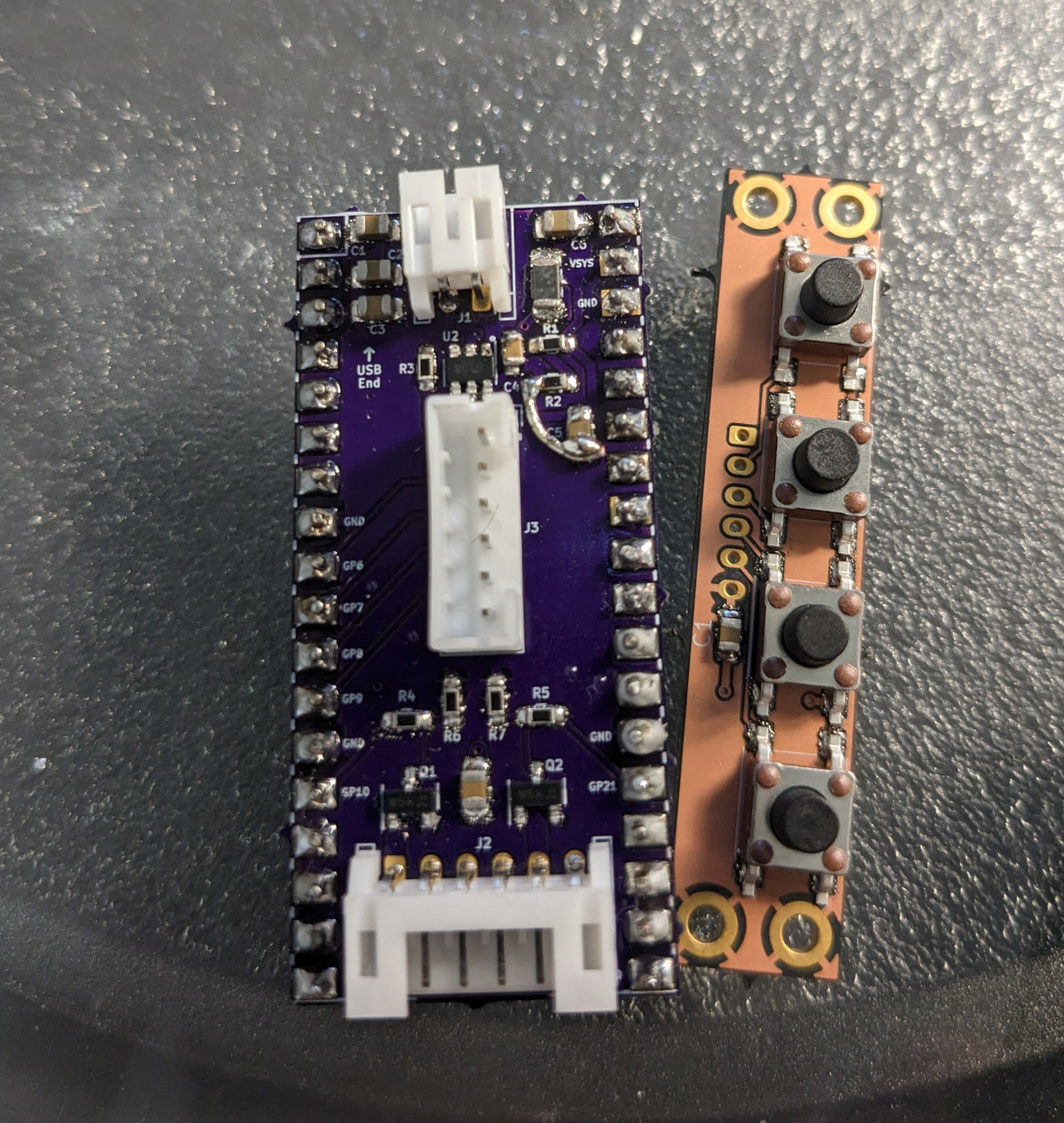
I plugged the hat into the Pico W, which was flashed with a debug firmware that flashes the LED at 2 Hz. I turned on the power supply, and after a short boot-up period, the LED on the Pico W started flashing. But then I noticed the CWWW hat was getting warm. Very warm.
After turning off the board, I saw the inductor had gotten so hot, it had nearly desoldered itself from the board. A quick inspection of its datasheet revealed the problem: I had chosen a part with a maximum 50 mA current draw - and the Pico W can draw far more than that on startup.
Between the missing ground connection and the inductor, I needed to make a new board revision. Despite the setbacks, I was still very pleased with how everything went. Sure, there were some design and part selection flaws, but to get nearly everything right on the first try felt pretty good.
I found a potential replacement part for the inductor, which had a specified current capacity of 900mA and a resistance of 238 mohms, half that of the one I purchased. Optimistic, I also went ahead and ordered a new set of boards with the corrected ground plane. After a quick turnaround on the inductors, I replaced the inductor and tried again. I found that while the board worked, the inductor still got unacceptably hot, with a laser thermometer reading 45c after a few minutes of operation. Unfortunately, this inductor was around the upper limit for inductors in 1206 sized packages - I would have to change to a larger part to get a higher current capacity and lower resistance, meaning another redesign of the board.
More Work on ESPHome YAML
While I patiently waited for new parts to come in, I had time to look at the ESPHome configuration I had previously written. I realized that I hadn’t even looked at handling the button inputs yet! Without them, the lamp would only be controllable through Home Assistant.
According to the ESPHome documentation, physical buttons should be implemented using the binary_sensor component, which is relatively straightforward:
binary_sensor:
   - platform: gpio
     id: button_bright_up
     pin:
       number: 6
       mode: INPUT_PULLDOWN

binary_sensor:
   - platform: gpio
     id: button_temperature
     pin:
       number: 7
       mode: INPUT_PULLDOWN

binary_sensor:
   - platform: gpio
     id: button_bright_down
     pin:
       number: 8
       mode: INPUT_PULLDOWN

binary_sensor:
   - platform: gpio
     id: button_power
     pin:
       number: 9
       mode: INPUT_PULLDOWN
So far so good. However, now I had to make some decisions. How many discrete brightness steps do I want, and do I want to have an input method for smoothly controlling the brightness and color temperature? I settled on the following:
Pressing the brightness up / down buttons would change brightness by 10%.
Holding the brightness buttons would smoothly change brightness at a constant rate of 1 percent every 3ms, which would bring the brightness of the lamp from 0% to 100% in just over 3 seconds (plus a small delay to detect whether it was a single press or a hold)
Pressing the color temperature button would change the color temperature by 500K. By default, it would start off by increasing color temperature on each press until the maximum color temperature is reached, then it would decrease color temperature until the minimum color temperature is reached, then reverse again. This ping-pong behavior is vastly different than the existing controller, which merely cycles between 3000K, 4500K, and 6000K.
Adding the brightness inputs is fairly easy, thanks to ESPHome’s dim_relative API for light objects:
   - platform: gpio
     pin:
       number: 6
       mode: INPUT_PULLDOWN
     id: button_bright_up
     on_click:
       min_length: 50ms
       max_length: 500ms
       then:
         - if:
             condition:
               light.is_on: lamp
             then:
               - light.dim_relative:
                   id: lamp
                   relative_brightness: 10%
                   transition_length: 0.5s
     on_press:
      - delay: 0.5s
      - while:
          condition:
            binary_sensor.is_on: button_bright_up
          then:
            - light.dim_relative:
                id: lamp
                relative_brightness: 1%
                transition_length: 3ms
            - delay: 3ms
You can see that if the button press is between 50 and 500ms, one brightness step is triggered, otherwise it continuously changes the brightness of the lamp in 1% increments.
Unfortunately, there is no equivalent function for color temperature in ESPHome. Furthermore, ESPHome uses mireds instead of Kelvin for color temperature, though at least it’s in floating point and doesn’t lose precision… Except it does lose precision on the Home Assistant frontend! This issue was already noted by others in the community. Worried that this issue would affect this project, I dove right in and found out that the Home Assistant ESPHome light entity did not have the helper functions defined to properly convert between floating point mired values and Kelvin. I submitted a pull request, so hopefully soon everyone using ESPHome to interface with color temperature adjustable lights will enjoy better precision when using Home Assistant.
Next Steps
With the first prototype board tested and required revisions noted, I can can now focus most of my effors on finalizing the configuration (making changes to ESPHome if required), and designing the enclosure for the project that fits in-line with the lamp, similar to the existing one. Part 3 should cover all this remaining work and show off the final prototype - stay tuned!