Raspberry Pi Pico W CWWW Controller - Part 3
It’s been some time since I documented the progress of my lamp project. But the good news is: the latest revision works perfectly! It just took a little bit more time and several more revisions than I expected.
Revision 1.1: Fixing the Ground
After discovering the missing ground vias (something I discovered in my last update, I quickly made a new revision and submitted an order with OSH Park. Unfortunately, while waiting for the new boards to come in, further testing with a bodged 1.0 board showed that even with a higher current inductor, the inductor still got uncomfortably hot, and I was not able to find a higher-current 1206-sized inductor. So, with that in mind, I set out to make another revision that had space for a 1210-sized inductor.
Revision 1.2: So Close, Yet So Far
Adjusting the design to fit a 1210-sized inductor required very little PCB rework, and I quickly got an order for the next revision boards and template. Having more confidence in preparing the boards, I was able to get them reflowed with a bit more ease this time. I then hooked up the boards and checked if they were visible in Home Assistant.
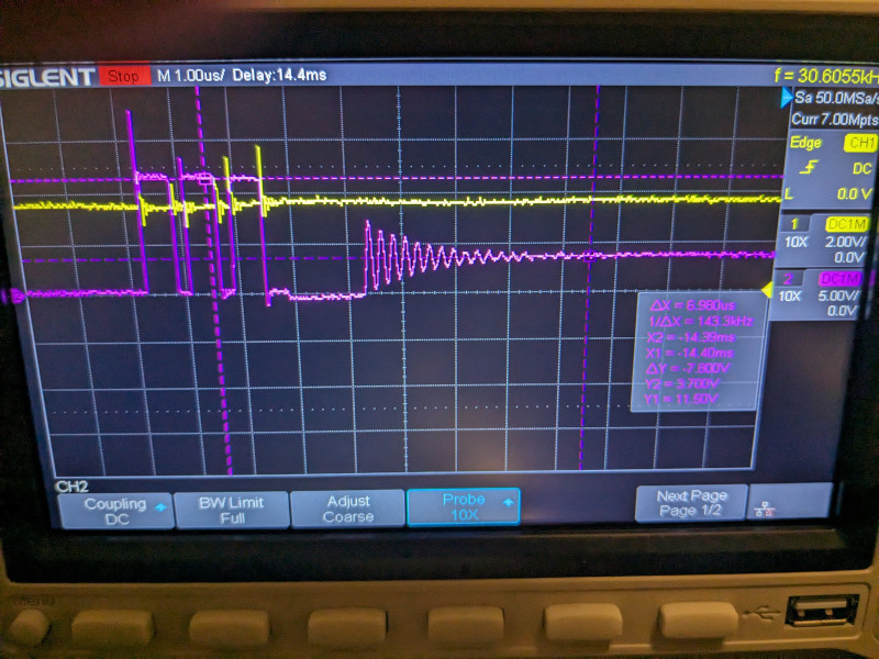
Unfortunately, while testing this revision, I started encountering very strange power behavior, almost as if the power output of the CWWW hat was browning out. Adding capacitors didn’t smooth out the voltage enough to maintain a high enough voltage to power the Pico, so in effect it would cause the Pico to hard reboot every second or two. Not idea for this application, to say the least.
After further testing, I found that the Pico wouldn’t even boot after plugging it into a USB port. I think at some point, either due to a faulty board or a short while I was probing, I managed to break the power circuitry. Oh well, at least Picos are cheap!
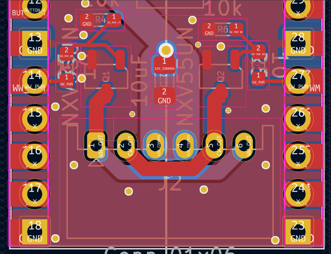
I also discovered one other issue: the transistor pinouts for the part I used were not the same as the generic KiCAD part, meaning that even if the rest of the board were working properly, it would never be able to properly control the PWM of the lights themselves.
I resigned myself to creating a new revision, hoping it would be the last…
Revision 1.3: It’s Aliiiiiive!
I started the v1.3 revision by correcting the footprint of the transistors in KiCAD; when I went to lay out the newly corrected part, I had to invert the orientation of the transistors. In the end, I feel as though the routing is slightly nicer than the previous revision (had the pinouts been correct)
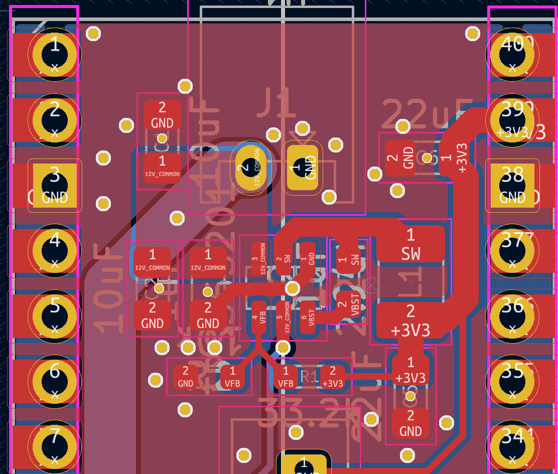
While I am fairly certain that my original power circuit layout would have worked fine, a friend of mine suggested more tightly conforming the layout to the suggested one in the datasheet. This suggestion mainly entailed putting the components closer together: the decoupling capacitors are now closer to the left side of the switching IC, and the bootstrap capacitor and inductor are now closer to the right side of the IC. Altogether, these changes shortened the switching loop. I also took my friend’s suggestion to add vias beneath all the capacitors, and add more ground vias in general, to reduce or eliminate any ground loops.
Eventually, I got the boards, parts, and got everything assembled. Given my experience on the previous revision, I tested much more cautiously, using a breadboard to test the board’s voltage before jumping the power over to a new, working Pico W. After I verified it booted, I carefully connected the lamp connector and…
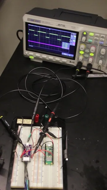
… It worked! Full, end to end control of both channels through Home Assistant and ESPHome!
I performed some other tests over the next few days, namely a long-term test to ensure that it could handle being powered for a long period of time, and some testing of the physical button functionality. All the buttons are detected, though some of the functions don’t work quite the way I want them to right now. At least with ESPHome, I can easily flash new firmware to fix any flaws!
Now comes the last part: putting it all together in a case. I have some experience with SolidWorks, so I put together a design that can fit all the components. Unfortunately, it’s a bit bigger than I’d like, due to the JST connectors and wiring. I think it might be easier to simply attach some pin headers with the same pitch to make it smaller.